|
|
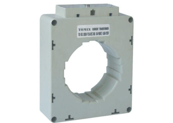
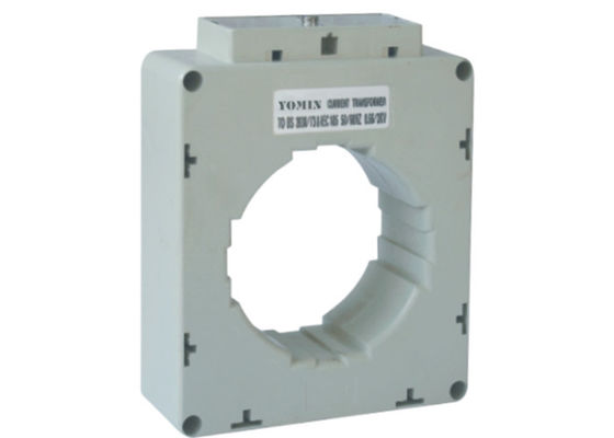
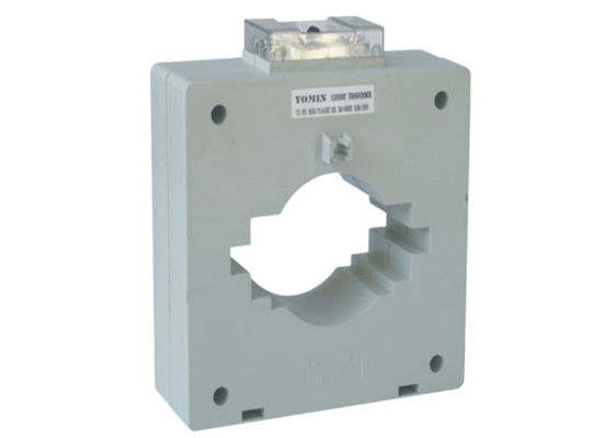
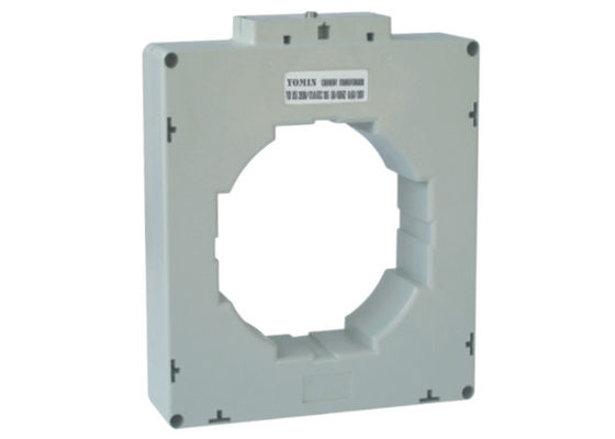
Low Voltage Window Type LV Current Transformers Toroidal Coil Structure
Product Details:
Payment & Shipping Terms:
|
| Coil Structure: | Toroidal | Coil Number: | 320 Turns |
|---|---|---|---|
| Phase: | Single Phase | Max System Voltage: | 720V AC |
| Frequency: | 50/60Hz | Accuracy: | 1.0 |
| Test Voltage: | 3kV AC (1min.) | Standards: | IEC60044-1, VDE0414-44-1, BS3938, BS7626 |
| Highlight: | Low Voltage Current Transformers,High Accuracy Current Transformer |
||
msq-85 Low Voltage Window Type Current Transformer / Instrument Transformer
Description :
MSQ Current Transformers(instrument transformer,Class Current Transformer)
in the AC circuit with the rated voltage value The series of current transformer can be applied to test, control, display and record the running of the electrical equipment, and to protect the equipment against the damage, in the AC circuit with the rated voltage value below 660V and the frequency of 50 - 60Hz. The current transformer can be also applied to form a complete set of mine transformer. The products comply with VDE 0414,BS 7626 and IEC 44-1 standard.
Selection of the Current Transformer
To select the current transformer correctly, the following points should be clarified:
- The application (for measuring or protection).
- The features of the working environment (Indoor or outdoor, operating temperature, air humidity etc….).
- Operation voltage and frequency.
- Range of the primary current (maximum and minimum of the current to be measured).
- Dimension of the cable or Bus bar.
- Data of the overload.
- Short circuit current.
- Specification of the measuring device associated with the current transformer (Accuracy, rated current, consumption etc…).
- The diameter and length of the cable, the cable which is used to connect the current transformer and associated measuring device.
Power Losses of the CT
In the practical application, the power generated by the primary current should be equal or bigger than the power requirement of the associated measuring device plus the consumption of the connecting line.
Losses in the line, PL:
This is the power loss, through heat, generated by current through the resistance RL in the cable, in the transformer’s secondary circuit.
Factors to be taken into account:
Secondary current: PL = RL / 2
Cable diameter: RL is inversely proportional to the square of the diameter cable length: RL is proportional to the length of cabling (there and back).
Power: The nominal apparent power (VA) with a specified power factor, which was supplied by the Current Transformer, to the secondary current with the assigned current when it is connected to its nominal load. Sc (VA) = Zc (/sn)2 According to Standards, for apparent power greater than or equal to 5VA, the power factor is 0.8 inductive. For apparent power less than 5VA the power factor is considered to be one (unity).
- Current Ratio..................................................................................30/5A
- Accuracy.........................................................................................Class 0.5
- Burden.............................................................................................See Selection Form.
- Security Factor................................................................................FS<5
- Max System Voltage.......................................................................720V AC
- Test Voltage.....................................................................................3kV AC. (1 min.)
- Frequency........................................................................................50/60Hz
- Rated Short-time Thermal Current (Ith)........................................Ith = 60 X In
- Rated Dynamic Current (Idyn).......................................................Idyn = 2.5 X Ith
- Continuous Overload.....................................................................1.2 X In
- Working Temperature....................................................................-25°C ~ +50°C
- insulation Rating.............................................................................Class B
- Housing Self-extinguishing Class.................................................VO
- Panel Mounting................................................................................Provided
- Hinged Sealable Terminal Cover....................................................Provided
- Standards.........................................................................................IEC/EN60044-1, VDE0414-44-1, BS3938, BS7626
Selection Form
| Item | Current Ratio | Rated Burden (VA) | Case Qty. | |
| Model | (A) | Class: 0.5 | Class: 1.0 | (Pcs) |
| MSQ-85 | 750/5 | 5 | 10 | 12 |
| MSQ-85 | 800/5 | 5 | 10 | 12 |
| MSQ-85 | 1000/5 | 7.5 | 10 | 12 |
| MSQ-85 | 1200/5 | 10 | 15 | 12 |
| MSQ-85 | 1500/5 | 10 | 15 | 12 |
| MSQ-85 | 1600/5 | 10 | 15 | 12 |
| MSQ-85 | 2000/5 | 15 | 15 | 12 |
| Item | Current Ratio | Rated Burden (VA) | Case Qty. | |
| Model | (A) | Class: 0.5 | Class: 1.0 | (Pcs) |
| MSQ-100 | 800/5 | 5 | 5 | 16 |
| MSQ-100 | 1000/5 | 10 | 10 | 16 |
| MSQ-100 | 1200/5 | 10 | 15 | 16 |
| MSQ-100 | 1250/5 | 10 | 15 | 16 |
| MSQ-100 | 1500/5 | 10 | 15 | 16 |
| MSQ-100 | 1600/5 | 10 | 15 | 16 |
| MSQ-100 | 2000/5 | 10 | 15 | 16 |
| MSQ-100 | 2500/5 | 10 | 15 | 16 |
| MSQ-100 | 3000/5 | 10 | 15 | 16 |
Note: Class and VA rating must be mentioned when ordering.
Feature
![]()
Dimension
![]()
Contact Person: Ms. Linda
Tel: 86-577-61616258
Fax: 86-577-61616258
-
Red Color Cast Resin Low Voltage Current Transformer Plate Fixed Installation
-
Class 0.5 CT Electric Current Voltage Transformer With Ammeter , High Accuracy
-
Small Split Core LV Current Transformers , Ac Ct Current Transformer Safety
-
SCT Split Core LV Current Transformers And Ring Type CT High Accuracy
-
Single Phase Low Current CT Current Transformer 100 5a For Metering System
-
Mini Lv Current Transformers , Weightless 25 / 5a Current Transformer Class 0.5


